Contents Catalog

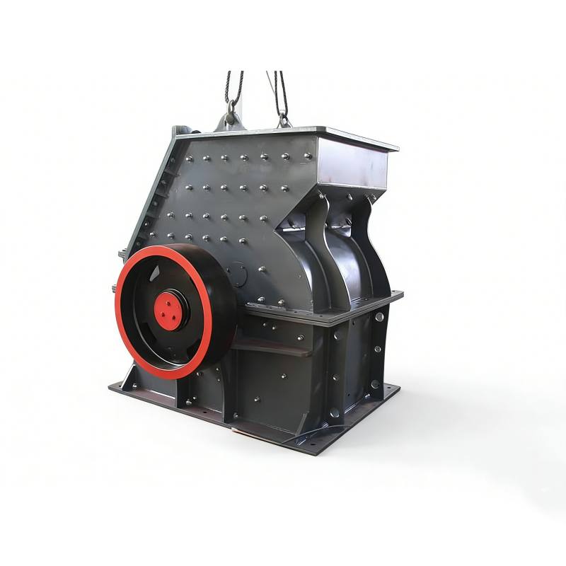
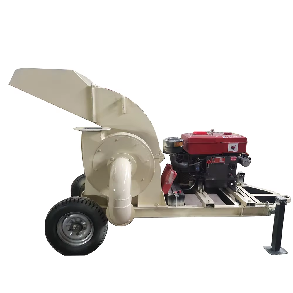
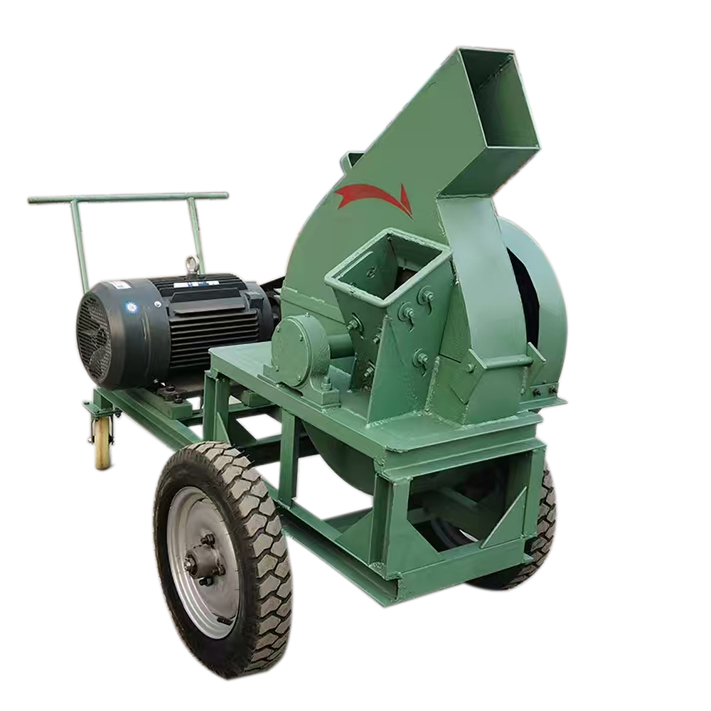
The compound cone crusher is an efficient crushing equipment primarily designed for the fine crushing of medium-hard or harder ores and rocks. Its working principle is based on compressing and crushing material between a fixed cone and a moving cone until the desired particle size is achieved. The design aims to provide high production capacity, low energy consumption, easy operation, and stable product quality.
Technical Parameters
- Production Capacity: 5–750 t/h
- Feed Particle Size: 35–300 mm
- Discharge Particle Size: 3–51 mm
- Applicable Materials: Iron ore, copper ore, marble, granite, etc.
- Application Fields: Mining, metallurgy, construction, etc.
Product Features
1. Hydraulic Adjustment System
Equipped with an advanced hydraulic system for rapid and precise adjustment of the crushing chamber, meeting various particle size requirements and improving production flexibility and efficiency.
2. Stable and Reliable Operation
Robust structure with optimally designed components ensures high stability and reliability, suitable for long-term continuous operation, maintaining production continuity and stability.
3. Multi-Layer Crushing Chamber Design
Adopts a multi-layer crushing chamber to increase material crushing cycles, effectively enhancing crushing efficiency and finished product quality.
4. High Energy Efficiency Ratio
Optimized crushing chamber structure and advanced hydraulic system reduce energy consumption, improving overall energy efficiency and meeting modern requirements for energy conservation and environmental protection.
5. Automation Control System
Some models feature an advanced automation control system for real-time monitoring and adjustment, improving production efficiency and operational convenience.
Working Principle
1. Feed and Distribution Plate
Material enters through the feed port and is distributed into the crushing chamber via the distribution plate.
2. Multi-Layer Crushing Chamber Crushing
Material undergoes primary and secondary crushing through compression and squeezing between the eccentric shaft and chamber walls.
3. Rotary Wall Thin-Layer Crushing
Material forms a thin layer via the rotating wall movement, further enhancing crushing efficiency and fineness.
4. Hydraulic Adjustment and Control
The hydraulic system adjusts the discharge port and crushing chamber size to control output particle size and production volume.
5. Sealing and Dust Prevention
Effective sealing devices prevent dust leakage, improving operational cleanliness and safety.
Compound Cone Crusher Technical Specifications
| Model | Cs90 | Cs155 | Cs240 | Cs350 | ||||||||||||
|---|---|---|---|---|---|---|---|---|---|---|---|---|---|---|---|---|
| Specification | 3Ft 900mm | 4 1/4Ft 1275mm | 5 1/2Ft 1650mm | 7Ft 2134mm | ||||||||||||
| Cavity Type | Fine | Coarse | Extra Coarse | Fine | Medium | Coarse | Extra Coarse | Fine | Medium | Coarse | Extra Coarse | Fine | Medium | Coarse | Extra Coarse | |
| Recommended Minimum Discharge Opening (mm) | 3/1″ (9) |
1/2″ (13) |
1″ (25) |
1/2″ (13) |
5/8″ (16) |
3/4″ (19) |
1″ (25) |
5/8″ (16) |
7/8″ (22) |
1″ (25) |
1 1/2″ (38) |
3/4″ (19) |
1″ (22) |
1 1/4″ (25) |
1 1/2″ (38) |
|
| Corresponding Feed Opening for Recommended Minimum Discharge Opening | B (Closed Side) (mm) | 3 5/6″ (83) |
6 3/8″ (159) |
6 1/2″ (163) |
4 3/8″ (109) |
7 1/2″ (188) |
8 5/8″ (216) |
9 1/2″ (238) |
7 1/2″ (188) |
8 1/2″ (213) |
9 5/8″ (241) |
13 1/4″ (331) |
10 1/8″ (253) |
12 1/8″ (303) |
13 3/5″ (334) |
16 3/4″ (425) |
| B (Open Side) (mm) | 4 1/16″ (102) |
7″ (175) |
7 1/8″ (178) |
5 3/8″ (137) |
8 1/4″ (210) |
9 5/8″ (241) |
10 3/8″ (259) |
8 3/8″ (209) |
9 5/8″ (241) |
10 3/4″ (269) |
14 1/2″ (368) |
11 1/8″ (278) |
13 3/8″ (334) |
14 3/4″ (369) |
18 1/8″ (460) |
|
| 3/8″ | (9mm) t/h | 50 | ||||||||||||||
| 3/8″ | (9mm) t/h | 50 | ||||||||||||||
| 1/2″ | (13mm) t/h | 65 | 65 | 120 | ||||||||||||
| 5/8″ | (16mm) t/h | 80 | 80 | 140 | 145 | 200 | ||||||||||
| 3/4″ | (19mm) t/h | 90 | 100 | 160 | 175 | 190 | 225 | 420 | ||||||||
| 7/8″ | (22mm) t/h | 100 | 120 | 170 | 190 | 215 | 250 | 450 | ||||||||
| 1″ | (25mm) t/h | 130 | 130 | 180 | 220 | 240 | 260 | 285 | 320 | 330 | 550 | 670 | ||||
| 1-1/4″ | (31mm) t/h | 150 | 150 | 200 | 250 | 275 | 300 | 325 | 370 | 390 | 680 | 800 | 870 | |||
| 1-1/2″ | (38mm) t/h | 180 | 180 | 280 | 325 | 335 | 360 | 420 | 460 | 475 | 800 | 890 | 930 | 970 | ||
| 2″ | (51mm) t/h | 385 | 395 | 460 | 500 | 525 | 1100 | 1200 | 1300 | |||||||
| 2-1/2″ | (64mm) t/h | 700 | 750 | 1400 | 1500 | |||||||||||
| Total Weight (kg) | 15000 | 26500 | 43276 | 67270 | ||||||||||||
| Motor Power (KW) | 6P-75 | 6P-160 | 6P-250 | 6P-350 | ||||||||||||
| Overall Dimensions (mm) | 2865 x 2000 x 2190 | 3300 x 2500 x 2940 | 4105 x 3280 x 3505 | 5110 x 4270 x 4350 | ||||||||||||